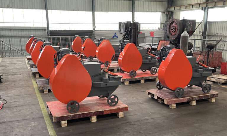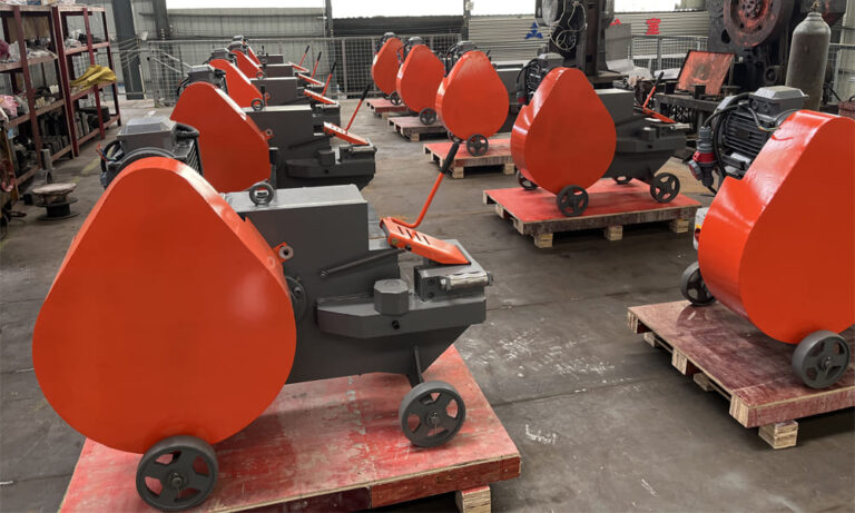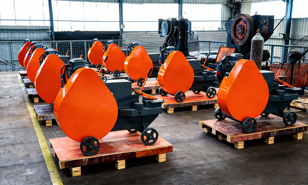
Italian-type C52 rebar cutting machine is a widely recognized solution for processing small- to medium-diameter steel reinforcement bars. Designed to cut hot-rolled round steel ranging from Ø10 mm to Ø52 mm, it is commonly used on construction sites as well as in rebar fabrication facilities. The machine integrates either a hydraulic drive system or a flywheel-based mechanical transmission, both built around the same fundamental concept: efficient power delivery, controlled blade movement, and secure material fixation.
Although the two drive configurations differ in their power sources and motion conversion methods, they share the hallmark characteristics of Italian-style cutters—compact structure, exceptional rigidity, and strong adaptability to varied working conditions. This overview focuses on three main aspects: overall structural design, drive-specific working principles, and the relationship between blade motion and power transmission.
1. Structural Framework of the Italian-Type C52 Rebar Cutting Machine
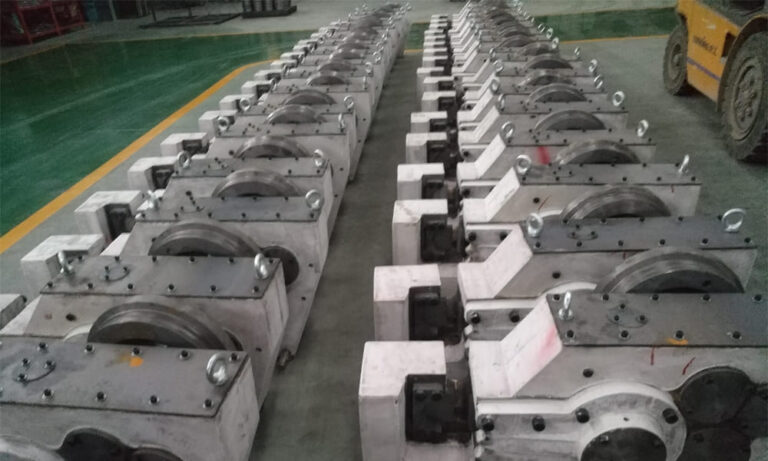
Both hydraulic and mechanical versions of the C52 are built upon a common structural platform consisting of a main frame, clamping device, cutting blade system, fixed blade seat, and scrap discharge channel. Differences between the two versions are limited to the power unit, transmission components, and the mechanism driving the moving blade. All components follow a modular design approach and utilize wear-resistant materials typical of Italian engineering standards.
Main Frame
The machine body is manufactured from a single-piece cast steel structure or, in enhanced configurations, from thick welded steel plates subjected to stress-relief treatment. Internal cavities accommodate the transmission or hydraulic systems. Shock-absorbing foot pads and anchor bolt holes at the base ensure stable operation, reducing vibration and preventing misalignment during cutting—an important distinction compared to conventional cutter designs.
Clamping System
The rebar is secured using a manual or semi-automatic V-shaped clamping mechanism. This system is mechanically synchronized with blade movement, automatically locking the material as the blade advances. High-manganese steel inserts provide strong grip across various bar diameters, preventing rotation or axial movement and ensuring a straight, uniform cut.
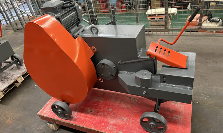
Cutting Blade System
The cutting unit consists of one fixed blade and one movable blade, both produced from high-alloy tool steel and heat-treated through quenching and tempering to achieve a hardness range of HRC 58–62. The stationary blade is mounted at the front of the frame, while the moving blade is connected to either a hydraulic cylinder rod or a mechanical crank-slider assembly. The blade edge is designed with a 30°–35° wedge angle to reduce cutting resistance and overall power demand.
Fixed Blade Holder and Clearance Adjustment
A detachable cast steel blade holder incorporates a fine-adjustment bolt that allows operators to regulate the clearance between the two blades, typically within 0.1–0.3 mm. This feature compensates for blade wear, minimizes adhesion of cut material, and prevents deformation at the cut surface. The adjustable clearance system is a signature feature of Italian-type machines, combining precision with ease of maintenance.
Scrap Discharge Chute
Located beneath the cutting area, a curved guide plate made from abrasion-resistant steel directs cut-off pieces away from the blades. This design reduces debris accumulation, prevents scattering, and protects the frame from repeated impact damage.
2. Flywheel-Driven Mechanical C52 Rebar Cutting Machine: Power Transmission and Motion Conversion
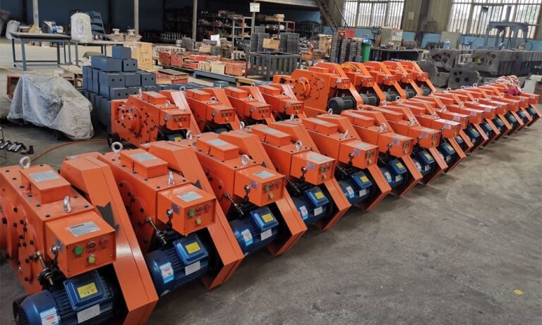
The flywheel-driven mechanical version represents the traditional and most widely used configuration of the C52. It operates on the principle of energy storage and release, making it suitable for sites with stable electrical supply and no reliance on hydraulic systems. Its advantages include fast response, high efficiency, and excellent performance in continuous cutting operations.
Key Drive Components
In addition to the shared structural elements, this version includes an electric motor, flywheel unit, gear reduction assembly, crank-slider mechanism, and clutch-brake system, all engineered to Italian design standards. Lightweight cast flywheels and helical gear reducers are often employed to reduce noise and mechanical stress.
-
Flywheel Unit: Acts as an energy reservoir. As the motor rotates the flywheel at high speed, kinetic energy is accumulated and released instantly during cutting, supplementing motor torque and enabling smooth cutting of larger-diameter bars.
-
Gear Reduction System: A two-stage reduction (helical gear followed by spur gear) converts high-speed motor rotation into low-speed, high-torque output. The use of helical gears ensures smoother engagement and extended component life.
-
Crank-Slider Assembly: Converts rotary motion into linear movement of the blade. It consists of a crankshaft, connecting rod, slider, and precision-machined guide rail. Tight tolerances ensure straight-line blade travel and cutting accuracy.
-
Clutch and Brake Mechanism: An electromagnetic clutch and mechanical brake control the cutting cycle. Pressing the foot pedal engages power transmission, while releasing it disengages the drive and applies braking force, stopping the blade and allowing precise, controlled operation.
Operating Cycle
When the motor is activated, the flywheel accelerates and stores kinetic energy. Power flows through the gear reducer, increasing torque before being transmitted to the crankshaft. As the crank completes one rotation, the connecting rod drives the slider forward along the guide rail, pushing the moving blade toward the fixed blade. At the same time, the clamping mechanism locks the rebar in place. Once the blades fully engage, the bar is sheared. Releasing the pedal disengages the clutch, activates the brake, retracts the blade, and releases the clamp, completing a single cutting cycle. Continuous pedal operation allows uninterrupted batch cutting.
Power Flow and Blade Motion Characteristics
Power Transmission Route:
Motor → Flywheel → Gear Reducer → Clutch/Brake → Crankshaft → Connecting Rod → Slider → Moving Blade
This direct mechanical transmission minimizes energy loss, achieving efficiency levels exceeding 85%. The stored flywheel energy provides high instantaneous torque, allowing single-stroke cutting of bars up to Ø52 mm.
Blade Movement Path:
The moving blade travels in a straight, linear reciprocating motion perpendicular to the bar axis. Stroke length is fixed at approximately 80–90 mm. During the cutting phase, blade speed increases as flywheel energy is released, reaching impact speeds of 1.2–1.5 m/s. This controlled motion ensures smooth shearing, reduced burr formation, and a clean cutting surface.