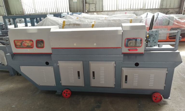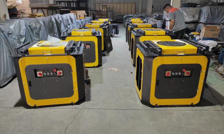
P52 Steel Bar Bender is vital equipment in rebar processing operations. Their primary function is to apply controlled mechanical force to steel bars, bending them into specified angles or shapes—such as stirrups, hooks, and frames—required by construction standards. Owing to their precision and efficiency, these machines are widely used in building construction, bridges, and other civil engineering projects.
I. Operating Principles
At its core, a P52 Steel Bar Bender converts electrical energy into mechanical force through a coordinated transmission system, ultimately producing plastic deformation in the steel bar. The operating process can be summarized as follows:
Power Generation
When the machine is started, the electric motor generates rotational energy, which is transmitted to the gearbox through a coupling.
Speed Reduction and Torque Amplification
Electric motors typically operate at high speed but low torque, which is inadequate for bending steel bars. The reduction gearbox lowers the rotational speed while significantly increasing torque, ensuring sufficient force is delivered to the bending mechanism.
Bar Placement and Fixation
The steel bar is positioned between the forming pin (mandrel) and the stopper pin on the working disc. The forming pin is adjusted to ensure the bar fits tightly against its surface, providing accurate control of the bending radius.
Bending Action
Driven by the transmission system, the working disc rotates, carrying the forming pin with it. As the disc turns, a continuous bending moment is applied to the steel bar. The stopper pin restrains radial movement, preventing slippage. Once the disc reaches the preset angle, the motor stops, completing the bending operation.
Return and Removal
The motor then reverses direction, returning the working disc to its initial position. The bent steel bar can subsequently be removed, and the machine is ready for the next cycle.
II. Main Structural Components and Their Functions
A P52 Steel Bar Bender is composed of several integrated components that work together to ensure accurate and stable bending performance:
-
Motor
Usually a three-phase asynchronous motor with power ranging from approximately 1.5 kW to 7.5 kW, depending on machine capacity. It provides the primary driving force and supports forward and reverse rotation for bending and reset operations. -
Gear Transmission System
Comprising a reducer and gear set made from hardened alloy steel, this system converts the motor’s high-speed, low-torque output into low-speed, high-torque motion suitable for bending operations. -
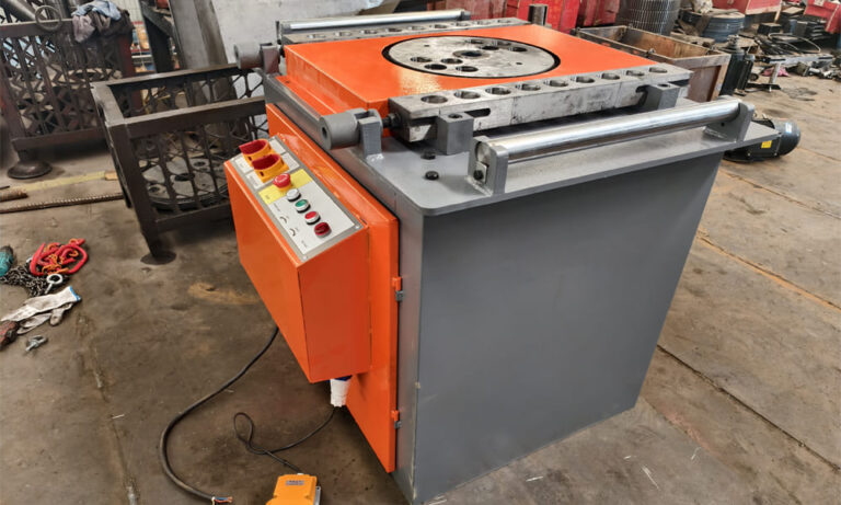
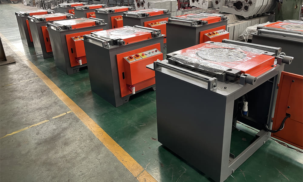
Working Disc
A circular disc, typically cast from iron or steel, with multiple adjustment holes. It serves as the main execution component, driving the forming tools and accommodating different bar diameters (commonly φ6–φ40 mm). -
Forming Pin (Mandrel)
Made from high-carbon steel with a smooth cylindrical surface, the forming pin defines the inner bending radius. Different pin diameters are used to meet rebar specification requirements and ensure compliance with standards. -
Stopper Pin
Installed on the machine body or disc perimeter, the stopper pin restricts bar movement during bending. Its position and height may be adjustable to suit various bend angles and configurations. -
Machine Body / Frame
Constructed from welded structural steel, the frame supports all components and absorbs operational forces and vibration. Anchor bolt holes allow the machine to be securely fixed to the floor for stable operation.
III. Key Coordination Factors
Efficient Power Transmission
Uninterrupted power flow from the motor through the gearbox to the working disc is essential. Proper gear meshing and alignment reduce energy loss, noise, and mechanical wear.
Precision of Positioning Components
Correct spacing between the forming pin and stopper pin is critical. Excessive clearance can lead to slippage, while insufficient clearance increases resistance and risks surface damage to the bar.
Control System Synchronization
Accurate coordination between motor control and disc rotation ensures consistent bending angles. Modern machines often employ limit switches or CNC systems to achieve precise angle control for repetitive operations such as 90° or 135° bends.